Fig. 1. Some mathematical operations that can be performed with operational amplifiers and ideal diodes. In each case the inverting (-) input to the op amp is used, and the noninverting (+) input is grounded.
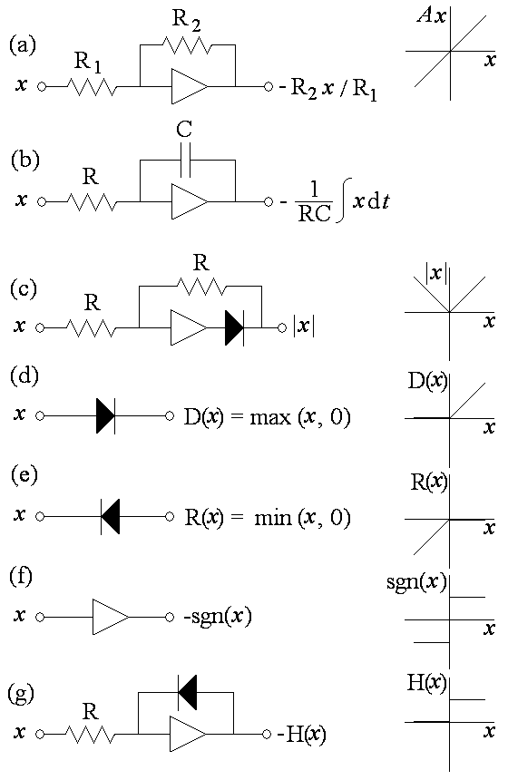
Fig. 2. Chaotic circuit implementation of Eq. (5) using inverting op
amps. The diodes are germanium, the battery is 1 V, the capacitors are
0.1 microfarads, and the resistors are 1 kilo-ohm except for the
variable
resistor, which should be adjustable from 1 to 2 kilo-ohms.
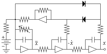
Fig. 3. Chaotic circuit implementation of Eq. (7) using three op amps. Capacitances are in microfarads, and all resistors are 1 kilo-ohm. The resistor in series with the battery can be increased to prevent saturating the op amps.
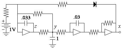
Fig. 4. Chaotic circuit implementation of Eq. (8) using three op amps. Capacitances are in microfarads, and all resistors are 1 kilo-ohm.
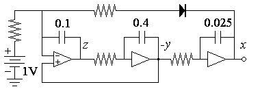
Fig. 5. Chaotic circuit implementation of Eq. (9) with the plus sign. Capacitances are in microfarads, and all resistors are 1 kilo-ohm except for R, which should be adjusted to give a current of 1 mA when the upper op amp is saturated.
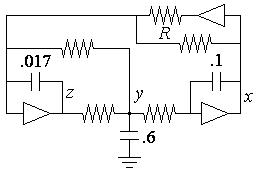
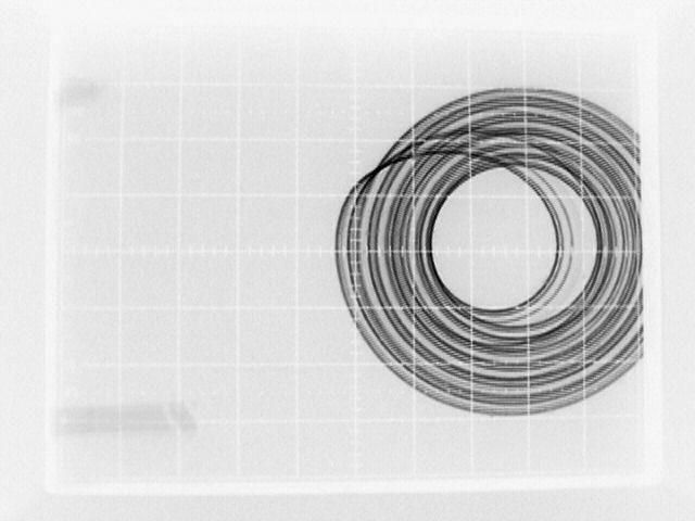
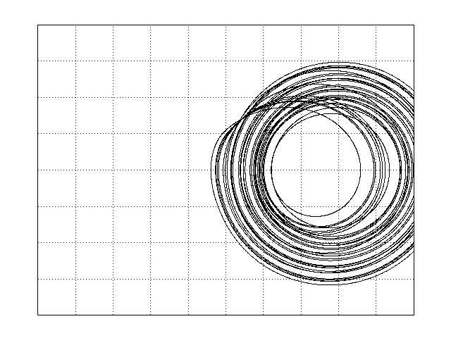
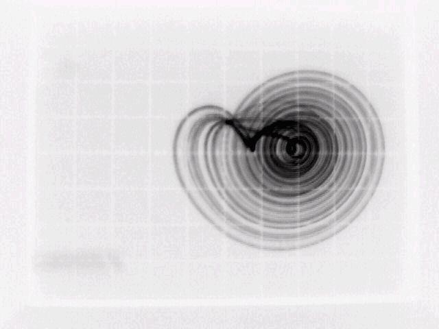
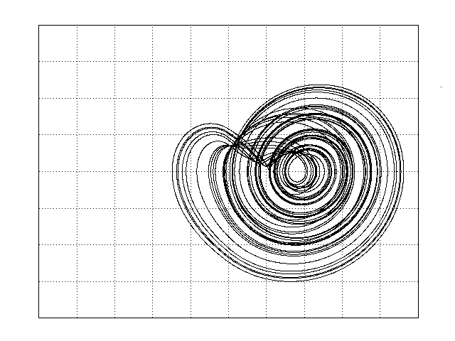
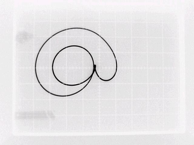
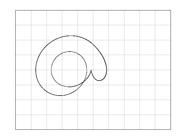
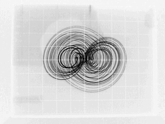
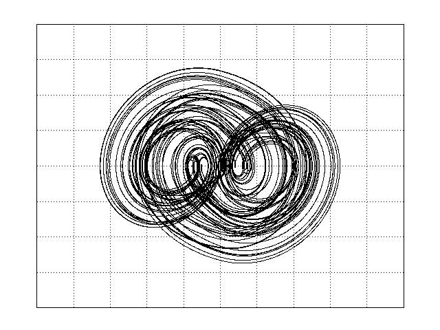
Fig. 6. Attractors produced by Eq. (10) in the x-dx/dt plane. In the left-hand column are oscilloscope traces for a circuit like Fig. 5 but with an extra inversion, and in the right-hand column are the corresponding numerical solutions on the same scale.
